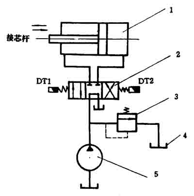
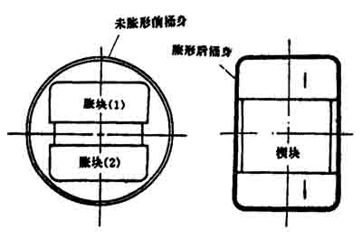
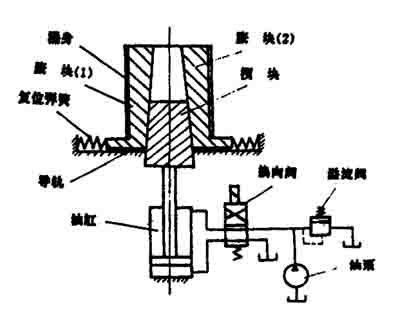
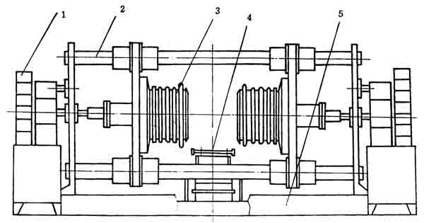
Theory and Practice of Steel Barrel Bulging Technology (2) Xin Qiaojuan Second, the barrel body bulging method There are many bulging methods in the barrel, and there are differences depending on the shape of the barrel, but the principle is the same. Figure 6 is a schematic view of a general cylindrical barrel ring bulging machine. The bulging method of Fig. 6 is the same as that of Fig. 4, and the expansion block 5 is pushed by the movement of the cone 9 to open outward. The power of the machine is added to the left end of the core rod by a hydraulic cylinder or cam mechanism. When working, first put the barrel into the barrel positioning sleeve 4, abut the frame positioning plate 3, and then start the action switch to move the core rod to the right, and the right side cone 9 on the core rod pushes the right slider 8 outward. The slider moves outward along the radial slide 6 and ejects the right expansion block 5, and the split expansion block expands outward to shape the right side ring of the barrel. Then the action valve is reversed, the core rod moves to the left, and the expansion block 5 is contracted inwardly back to the original position by the return spring 7, and the core rod moves over the intermediate position (ie, the position shown), and continues to move to the left to make the left cone block Push the left slider to expand the left expansion block outward and shape the left ring rib. Finally, the action valve is reversed, and the core rod returns to the middle position to remove the bulging barrel. Figure 7 Simplified schematic diagram of the hydraulic transmission of the bulging machine 1-hydraulic cylinder; 2-three-position four-way electromagnetic reversing valve (M type); 3-relieving valve; 4-fuel tank; 5_ oil pump. Figure 7 is a schematic diagram of the hydraulic drive of the bulging machine. As can be seen from the figure, when the electromagnet DT1 is actuated, the spool moves to the right, the piston of the hydraulic cylinder also moves to the right, and the core rod moves to the right; when the DT1 is de-energized and the DT2 is energized, the spool is reversed to the left. Then, the spool goes over the neutral position to the left position, so the piston moves to the left again, and the moving core rod also moves to the left; when the two electromagnets are not charged, the spool is in the neutral position, and the hydraulic oil is low pressure back to the tank. This is exactly the work process required for the bulging machine. Fig. 8 is a schematic view showing the principle of bulging of a rectangular square barrel. The barrel is cylindrical before the bulging, and the barrel becomes rectangular after the bulging. See Figure 9 for a schematic diagram of the rectangular barrel bulging machine. The bulging machine is mainly composed of a lump, a wedge, a cylinder and a hydraulic system. When the reversing valve is not energized, the wedge is in the lower position; when the reversing valve electromagnet is energized, the reversing valve is reversed, the cylinder piston is ascending, and the wedge forces the expansion block to move to both sides to expand the barrel into a rectangular shape. When the reversing valve is reversed again, the wedge descends and the expansion block moves toward the center under the action of the return spring, and the swollen barrel can be removed. Figure 8 Schematic diagram of the bulging of a rectangular barrel Figure 9 Schematic diagram of the bulging machine As shown in Figure 10, the flanged, expanded and expanded corrugated combined unit. The seam-welded barrel body is conveyed to the processing position by the conveying device, and the left and right fluffing expansion heads are hydraulically driven into the barrel body, and the cuffing process is first completed, and then the mold is squeezed and the cuffed head expands the cylinder to move through the core. The expansion rib cone on the shaft and the mandrel, the expansion bellows module pushes out the expansion rib module, and then pushes the expansion bellows module to complete the expansion and bulging process, see Fig. 6. The machine is equipped with a chain conveyor, generally controlled by PC. In the bulging process, it is generally required that the formed parts should conform to the process size requirements, and be rounded, uniform, and cracked (beyond the bulging limit), bursting and other defects. At present, the more advanced cone-shaped bucket is also the bulging technology. Because of its typical and unique molding theory, we will discuss it in detail. Figure 10 Mold extrusion flange, expansion rib, expansion and corrugation machine 1-hydraulic device; 2-guide column; 3-flange expansion head; 4-conveyor; 5-base Fixed furniture,loose furniture,for decoration,furniture villa Work with Leading Villa PinSheng hotel furniture , https://www.pinshotelfurniture.com


