Diamond Painting, also known as Diy Diamond Painting, is an organic combination of exquisite and shining artificial crystal flat-bottomed round diamonds (some square diamonds) and well-designed patterns. Paste it on the corresponding color point on the canvas, thus completing the paste of a diamond, you can get started in a few minutes, and then slowly fill in each color area, a 40CM*40CM diamond painting only takes 2 hours It's done in about a minute. With the continuous development of diamond painting, it has now extended to innovative products such as 3D diamond painting and 5D diamond painting. Diamond Painting,5d Diamond Painting,Diy Diamond Painting Dongguan Junkai Packaging Products Co., Ltd , https://www.diystoragecases.com
In recent years, the application of foreign card machine linkage refueling system has developed rapidly in technology. Mobil's Speed ​​Pass adopts non-contact radio frequency identification technology and has been widely applied. Israel's OTI's card-based linkage refueling system using contactless radio frequency identification technology has also been applied in many countries. Therefore, in view of the refueling status of the internal combustion engine of China's Locomotive Depot, combined with the Ministry of Railways' fuel management requirements for locomotives, this paper proposes that the automatic fuel distribution part can automatically control the start and stop of the oil pump according to the set fuel quantity; the oil quantity is recorded and displayed in real time, and stored. The refueling information required by the refueling report is transmitted to the upper computer at the same time; the fuel pressure detection of the pipeline ensures the safety of the oil circuit; the oil temperature detection module performs real-time detection on the oil temperature to ensure the accuracy of the calculated oil quantity; automatic/manual switching, Ensure that the oil control is absolutely reliable, and adopt the intelligent IC card management and reading and writing module to make the fueling system safe and perfect. It also proposes to collect the fueling data of each fueling point in the fuel management information system, and automatically generate various statistical reports. The locomotive segment computer is connected to the local area network.
1 Refueling system
The fueling system is divided into two parts: the automatic fuel delivery control system and the fuel data management system. The overall system architecture is shown in Figure 1.
Figure 1 The overall structure of the fueling system 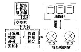
1.1 Automatic fuel release control system
The main functions of the system are:
1) According to the set fueling amount, the start and stop of the oil pump can be automatically controlled, and the solenoid valve of the corresponding control line can be opened and closed.
2) Record and display fuel flow in real time.
3) Record and store the refueling information required in the iron oil 7 report, such as the locomotive number, the number of trains, the amount of fuel, the start and end time of the oil, the oiler and the driver's order, etc., and transmit the information to the upper PC. 4) Ic card recording function: The driver can use the Ic card to store information, including the driver number, the driver's order number, the time of each oiling, the type of oil, and the amount of oil. 5) Monitoring the fuel pressure of the pipeline to ensure the safety of fueling. Hey. 6) Automatic/manual switching to ensure the reliability of the fueling control system.
1.2 Fuel Data Management System
The main functions of the system are:
1) Collect the fueling data of each fueling point and automatically generate various statistical data, such as weekly report, monthly report, ten-day report and annual report data.
2) The generation of iron oil report can be transmitted to the computer local area network in the segment for each department to call and consult.
2 Design of automatic fuel delivery control system
The computer system of the fuel dispenser adopts the industrial control machine of PC104 bus, which is composed of the motherboard C45, the interface board PCM5111, the single-chip keyboard, the IC card interface board and the on-site signal interface board, as shown in Fig. 2. 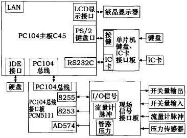
2.1 Field signal interface board design
The on-site signal interface board is the interface board developed and designed in this paper. Since the flow pulse output signal of the flow meter is not the standard CMOS_3 level, and the input X/output of the switch signal is not isolated, the board is specially designed for pulse signal. The shaping and level shifting uses opto-isolation for the input/output design of the switch to isolate the ground wire of the computer and the ground wire of the device such as the field relay to achieve anti-interference. In this way, the power supply of the entire computer is divided into computer system power supply (+5V, +12V, a 12V and ground) and field relays (+12V and ground), which are completely independent power supplies. The field signal interface board is connected with the on-site switch output signal, the flow meter pulse signal and the analog signal output from the pipeline pressure sensor, and then isolates, transforms and shapes the corresponding signal, and then transmits it to the other side of the interface board, thereby connecting the PC104 bus. Interface board PCMS11.
2.2 MCU IC card interface hardware design
In each locomotive section, in order to facilitate the management and recording of the locomotive fuel quantity, each driver is equipped with an Ic card, which stores the driver's job number and password, and also records the amount of oil per refueling. When refueling, the driver first inserts the IC card, the tanker automatically enters the interface displaying the IC card number, and finds the job number from the network database. If it exists, the next step prompts to enter the password, otherwise it is required to re-enter the card number. If the password is correct, you can refuel. If the password is entered incorrectly three times, the system will automatically cancel the refueling operation. Figure 3 shows the hardware design circuit of the interface between the 24C64IC card and the microcontroller. 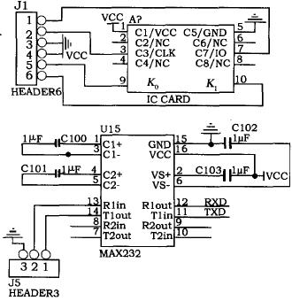
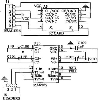
Figure 3 IC card and microcontroller interface schematic
The P1.1 port and the P1.0 port of the MCU are respectively connected to the clock line and the data line of the Ic card, and the IC card is controlled to read and write through the two lines. In addition, in order to judge whether the Ic card is inserted, the two contacts K0 and K1 of the Ic card are connected to +5V, and the other is connected to the P1.2 port of the single chip microcomputer. When the Ic card is inserted, the two contacts close and P1.2 El is high. Therefore, by detecting the level of P1.2 El, it is possible to know whether or not the IC card is inserted. In Fig. 3, either of the foot 5 and the foot 6 of J1 is connected to the foot 5 of J2, and the other is connected to the foot 4 of J2.
The data read from the IC card is sent to the host computer, and the data sent from the host computer is also written into the IC card. This function is realized by the string E1, and the serial design is used to transmit the string E1 with the MAX232. The chip is a dual-group driver/receiver with a capacitive voltage generator that provides EIA/TIA-232-E levels when powered from a single 5V supply. Each receiver will be EIA/TIA-232. The E-level inputs are converted to 5V TYL/CMOS levels, and each driver converts the TYL/CMOS input level to EIA/TIA-232-E level. In the circuit design, only the three lines of transmitting RXD, receiving TXD and ground GND can be connected. Since the I C bus is connected to the El circuit, the open circuit is open, so the bus is connected to a 10k pull-up resistor.
2.3 Microcomputer Ic card interface software program design
In the IC card software program design, first determine whether the IC card is plugged in, plug in and read the driver ID number in the Ic card, and store it in the fixed RAM in the chip. Then check the status of the serial port and perform different operations according to the received status flag. When the host computer wants to receive the driver's job number, it sends the data to the host computer; or receives the fueling information sent by the host computer and writes the Ic card. The program flow is shown in Figure 4. 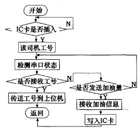
The Ic card capacity used in this system is 8k, and four kinds of data are stored internally: the driver number, the driver password, the number of groups that have stored fuel information, and the fueling information for each time. The position of the first three data in the IC card is fixed, and the values ​​of the job number and password are constant, but the group value of the fueling information is incremented by one for each fueling message. Each time you write a fueling message, its address is calculated by calculation.
For example, if the number of stored groups is set, the address of the first group of fueling information is stored, and a group of fueling information is stored in 16 bytes (including time: year, month, day, hour, minute; fueling type; fuel or lubricating oil) The number of refueling), the address of this refueling information should be: Y: M + 16X. When Y is larger than the capacity of the IC card, it is stored again from M.
If the driver's job number is stored at the IC card address of 0030H, the work number can be read by the following four statements:
Sla=0×0a9; / Read device address is 0 x0a9 /
Subah=0×00; / high address /
Subal=0×30; /low address /
ISendStrg(uchar sla.uchar subah.uchar subal, uchar s,1); The function of the subroutine ISendStrg is to read the value of nO bytes from a certain address (the address is suba) from the chip with the device address sla. The read content is placed in the storage area pointed to by S. This function returns a bit value. If it returns 1, it indicates that the read is successful. The function prototype is: bit ISendStrg(uchar sla, uchar subah, uchar subal, uchar}S, uchar no)
3 Fuel Information Management System Design
The core of the fuel information management system is to collect the personal information of the fueling data and the driver of the refueling locomotive in real time, and automatically generate various statistical data, such as weekly, monthly, ten and annual reports, and It is connected to the segment computer to realize remote transmission and sharing. The system accepts the refueling data transmitted by the lower computer mainly by relying on the local area network, and interacts with the PC104 tanker as a server. The program is independent of the specific data, which makes the program stable and versatile, and will not change due to changes in the customer's environment. The fueling record of the lower computer is periodically refreshed, so that the data is transmitted in time and accurately, and then stored in the database. The system is programmed with C+Builder5.0 and SQL Sever 2000.
At present, the system has been successfully applied in the Zhengzhou Railway Bureau's Yubei and Zhijiang Locomotive Depots, Nanchang Railway Bureau Yingtan and Xiangtang Locomotive Depot.
Locomotive IC card automatic fueling management system
Whether the supply, management, use and transmission of locomotive fuel are standardized, the control and saving of locomotive fuel consumption are crucial to cost control and efficiency improvement.